k j

Toward the Digital Design Studio: Large Display Explorations

Azam Khan, Justin Matejka, George Fitzmaurice, Gord Kurtenbach, Nicolas Burtnyk, Bill Buxton
January 2009 · Human–Computer Interaction (HCI)
Toward the Digital Design Studio: Large Display Explorations

Abstract

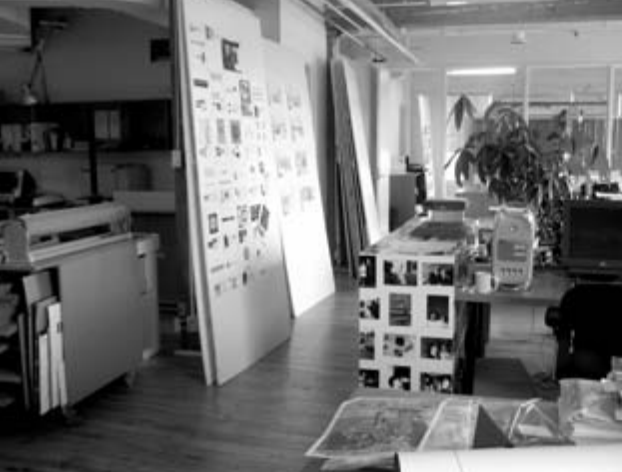
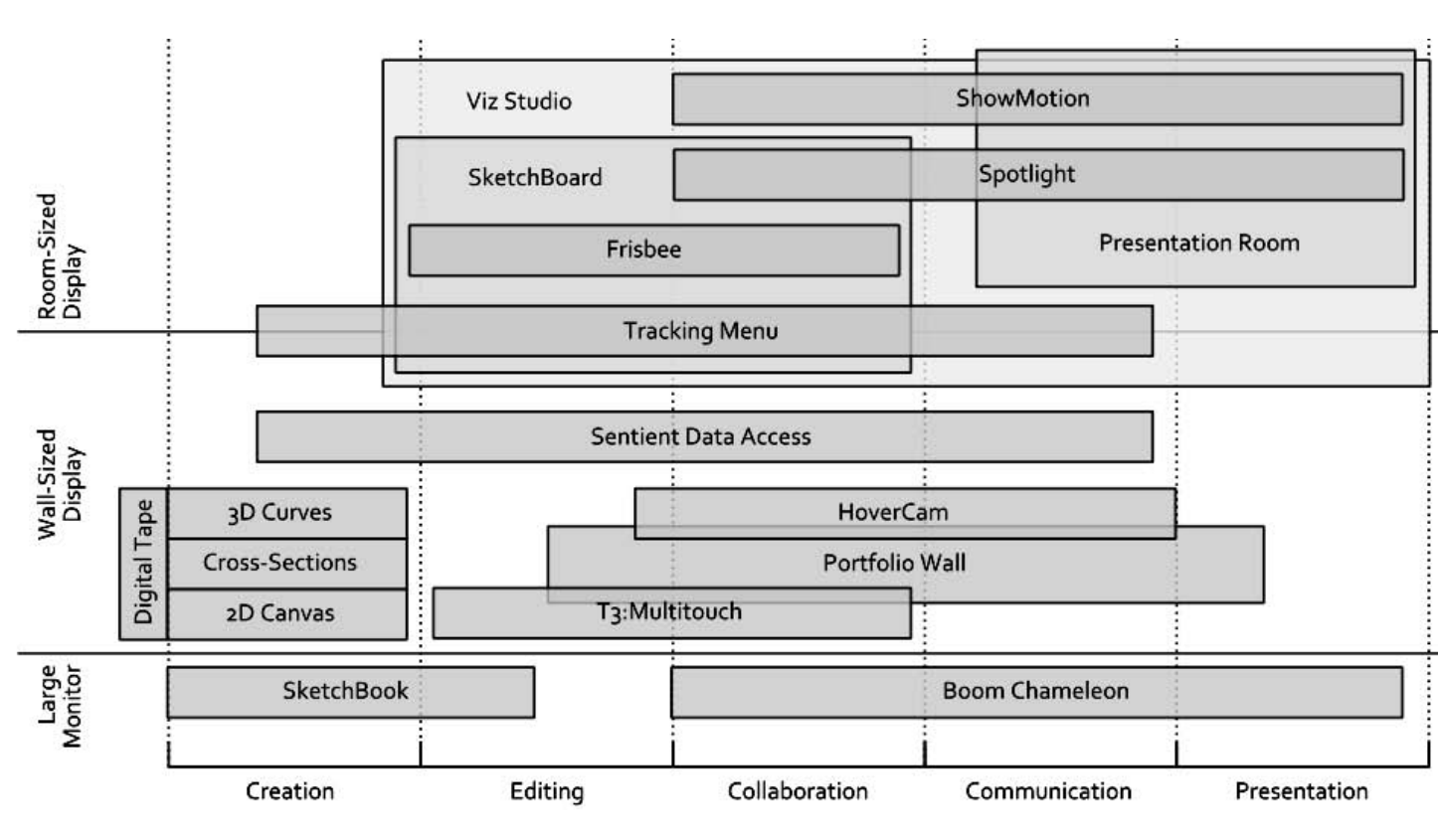
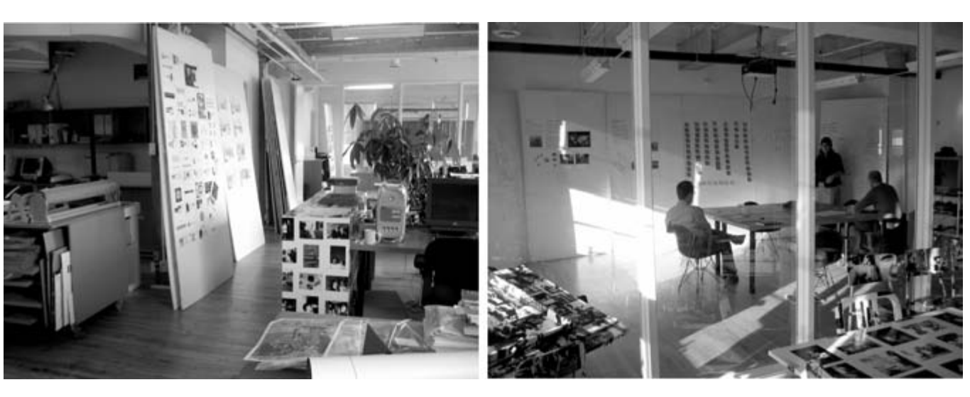
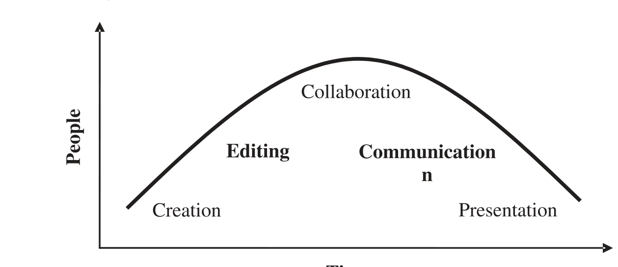
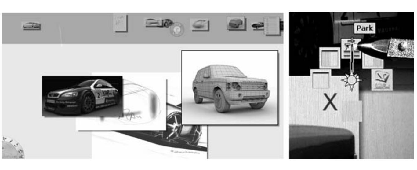
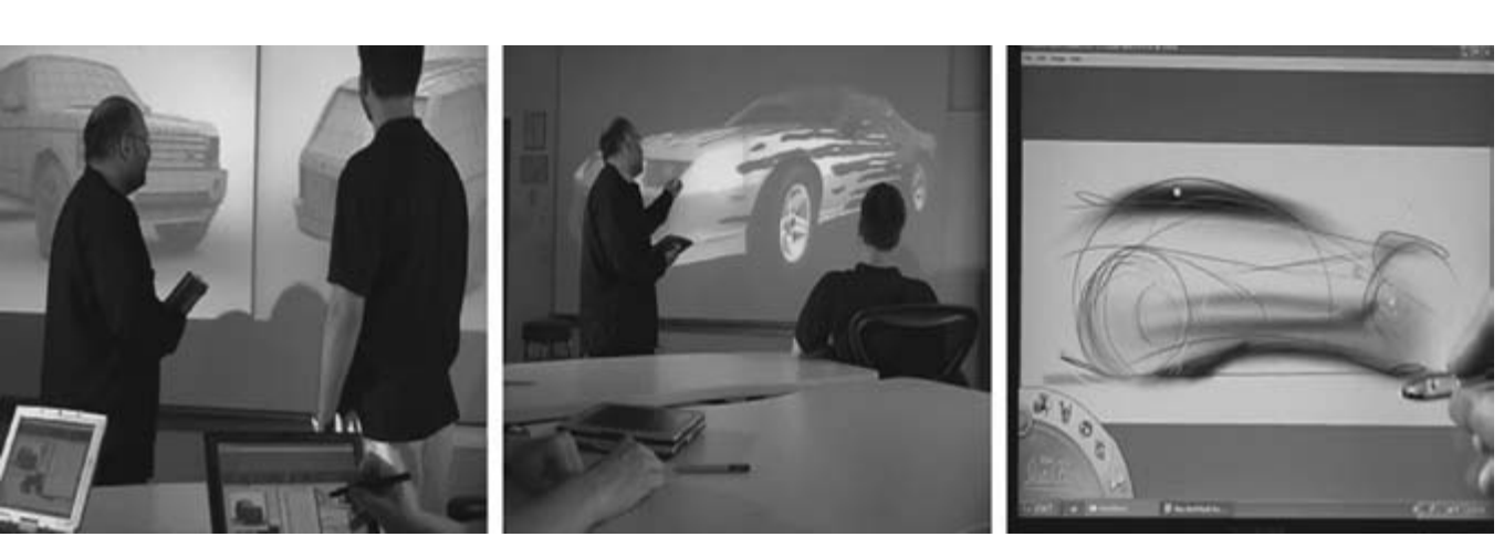
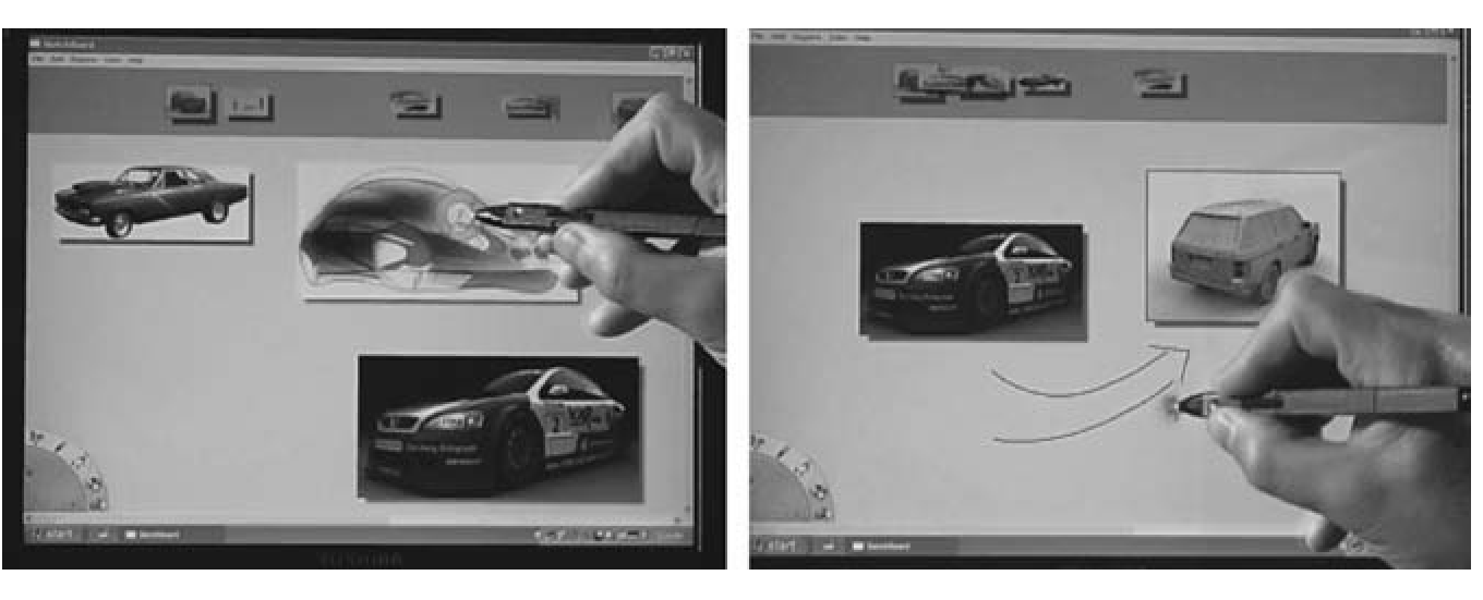
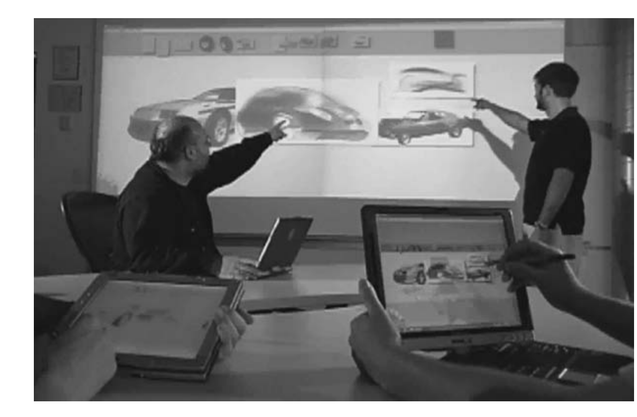
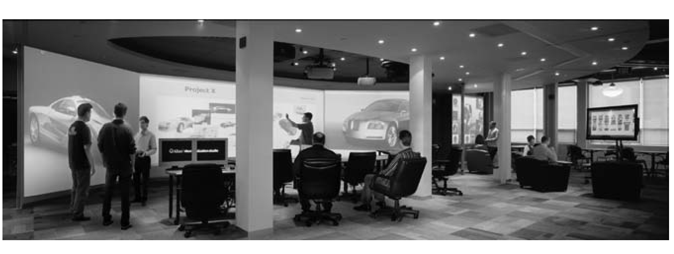
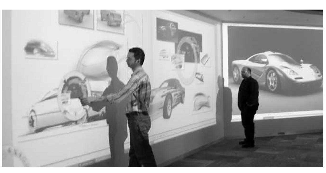
Inspired by our automotive and product design customers using large displays in design centers, visualization studios, and meeting rooms around the world, we have been exploring the use and potential of large display installations for almost a decade. Our research has touched on many aspects of this rich design space, from individual tools to complete systems, and has generally moved through the life cycle of a design artifact: from the creation phase, through communication and collaboration, to presentation and dissemination. As we attempt to preserve creative flow through the phases, we introduce social structures and constraints that drive the design of possible point solutions in the larger context of a digital design studio trail environment built in the lab. Although many of the interactions presented are viable across several design phases, this article focuses primarily on facilitating collaboration. We conclude with critical lessons learned of both what avenues have been fruitful and which roads to avoid. This article lightly covers the whole design process and attempts to inform readers of key factors to consider when designing for designers.

Figures

Figure 1. A mapping of systems grouped by display-size (vertical) versus design stage (horizontal).
Figure 2. A design studio workshop (left) and meeting room (right) (photography by Ilene Solomon, courtesy Bruce Mau Design).
Figure 3. Design artifact life cycle. ime
Figure 4. The workspace of a graphic designer.
Figure 5. Sketches from (left) automotive design and (right) fashion design.
Figure 6. Sketchbook on a Table PC.
Figure 7, An automotive designer using the tape drawing technique, and our digital ver- sion (from Balakrishnan et al., 1999).
Figure 8. (a) Cross-section modeling on large displays (from Grossman et al., 2001); (b) creating principle 3D curves on large displays (from Grossman et al., 2002).
Figure 9. Left to right: Drawing a curve and extruding it to be a 3D curved surface. Draw- ing a curve on an orthographic view of the curved surface (from Grossman et al., 2002).
Figure 10. Principle 3D curves for the Dodge Viper together with a photograph of a scale model of the car (from Grossman et al., 2002).
Figure 11. Trial environment for our digital design studio prototype (from Fitzmaurice et al., 2003).
Figure 12. (Left to right): The Boom Chameleon, the Boom Chameleon as a 3D podium, and the Elumens Vision Dome (from Fitzmaurice et al., 2003).
Figure 13. The Portfolio Wall (from Buxton, 2007).
Figure 14. SteeringWheels, ViewCube, and ShowMotion.
Figure 15. SteeringWheels (left) exterior navigation, (center) interior navigation, right (both).
Figure 16. (a) HoverCam camera motion path approaching and turning to follow the surface of the object, (b) HoverCam camera motion path and camera look-at direction in an “interior” concave shape, and (c) the HoverCam algorithm showing the Restricted Field of View (FOV) and the Obstacle FOV looking for obstructions to help turn the camera (from Khan et al., 2005).
Figure 17. (Left) Before and after clicking the highlighted corner. (Right) Expanded hit areas for boundary buttons. Clicking anywhere within the green regions will select the corresponding button.
Figure 19. (Left) Sketchboard interface; (right) marking menu with user selecting “park” with the pen.
Figure 20. Sketchboard (left) Compare, (middle) maximize, (right) open in Sketchbook Pro.
Figure 21. Working on Sketchboard from the TabletPC. (Left) using tracking menu; (right) drawing directly on the board (via the TabletPC).
Figure 18. Sketchboard on a number of TabletPCs and a large displays.
Figure 22. The Visualization Studio in Toronto (from Fitzmaurice et al., 2005).
Figure 23. Using the Frisbee with Sketchboard on a 20-foot display (from Khan et al., 2004). Note. The frisbee consists of a telescope and a target. The target pink ring (top right) can be panned and scaled by using controls, under the users hand, on the pink ring in the telescope (bottom left).
Figure 24, (Left) The Telescope contains controls for a “position control” and a “remote control” ring with four “transfer channels” along the perimeter (from Khan, et al., 2004). (Right) The user can click on a remote object within the telescope display and drag it through a transfer channel to the local space.
Figure 25. (Left) The Spotlight technique on a large wall-sized display (enhanced image). (Right) Spotlight components (exterior region, spot edge, spotlight interior region, cur- sor; from Khan, et al., 2005).
Figure 26. A panoramic (composite) image of the Presentation Room.
Figure 27. Presentation Room schematic. Inset: Components of the Progress Clock: (a) elapsed time, (b) slides already displayed, (c) current slide, (d) slides not yet seen.

BibTeX

@article{Khan16042009,
author = {Azam Khan and Justin Matejka and George Fitzmaurice and Gord Kurtenbach and Nicolas Burtnyk and Bill Buxton},
title = {Toward the Digital Design Studio: Large Display Explorations},
journal = {Human–Computer Interaction},
volume = {24},
number = {1-2},
pages = {9--47},
year = {2009},
publisher = {Taylor \& Francis},
doi = {10.1080/07370020902819932},


URL = { 
    
        https://doi.org/10.1080/07370020902819932


},
eprint = { 
    
        https://doi.org/10.1080/07370020902819932


}

}