k j

Transformer-Based Interfaces for Mechanical Assembly Design: A Gear Train Case Study

Mohammadmehdi Ataei, Hyunmin Cheong, Jiwon Jun, Justin Matejka, Alexander Tessier, George Fitzmaurice
January 2025 · arXiv preprint arXiv:2504.08633 (arXiv)
Transformer-Based Interfaces for Mechanical Assembly Design: A Gear Train Case Study

Abstract

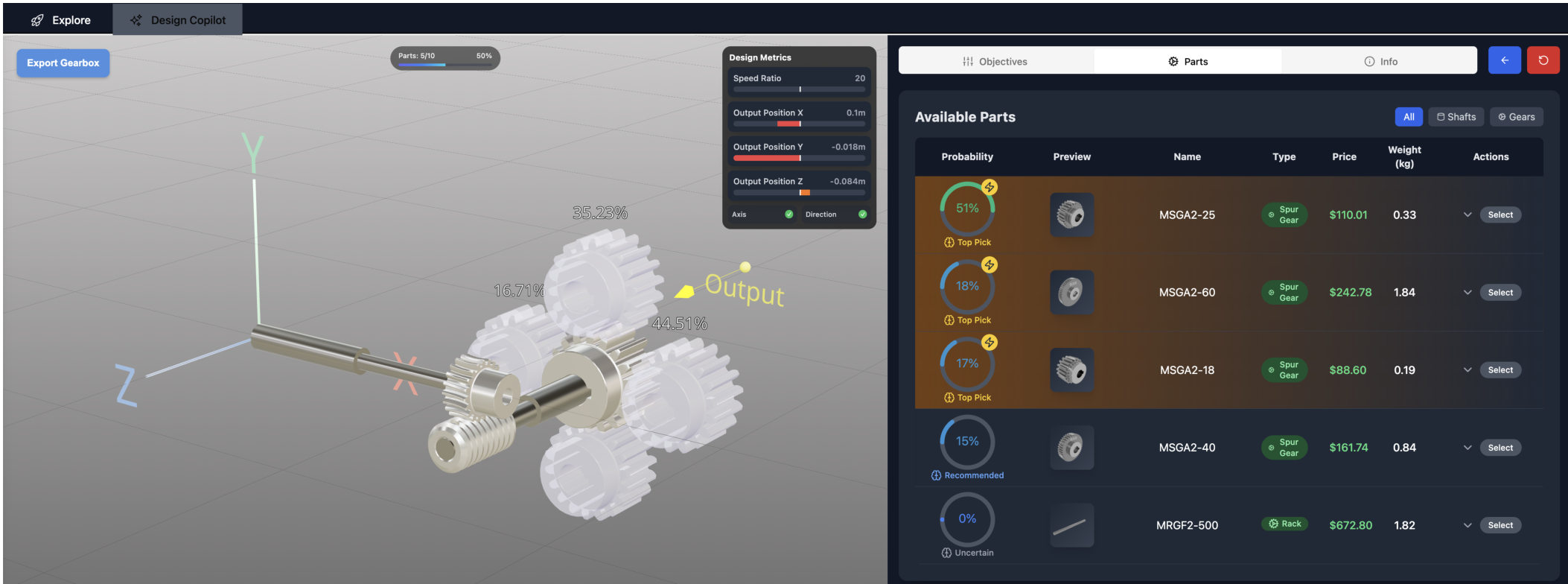
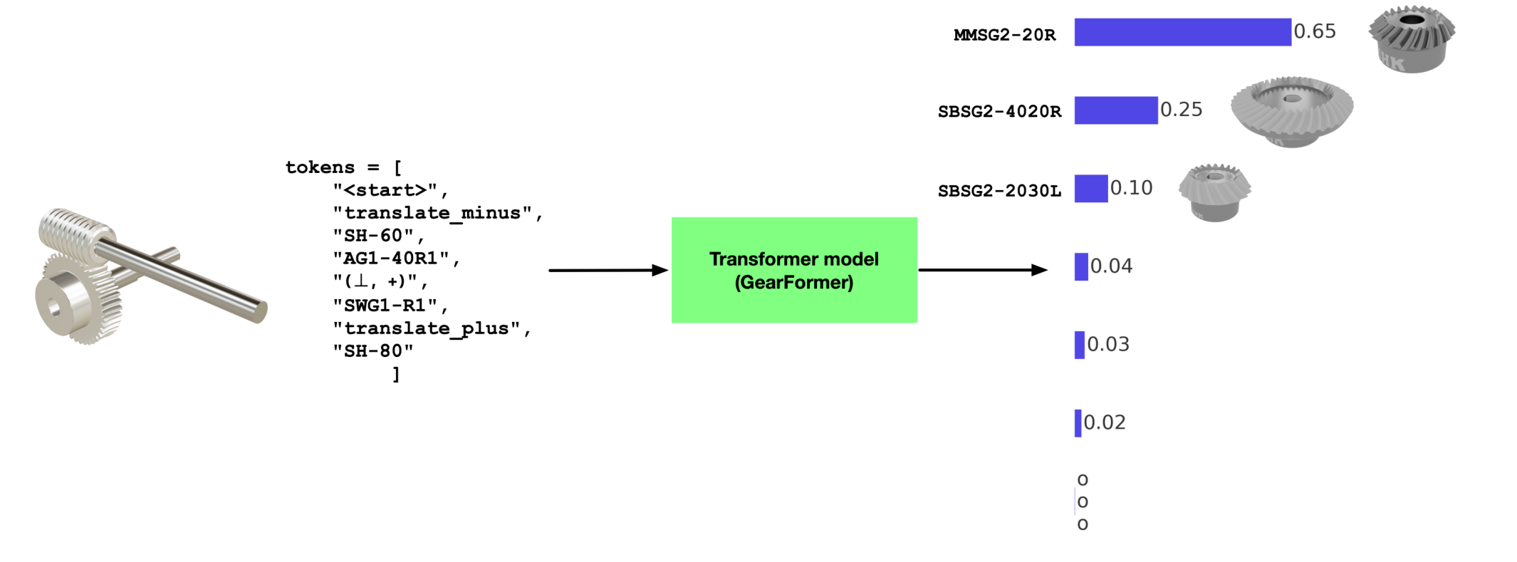
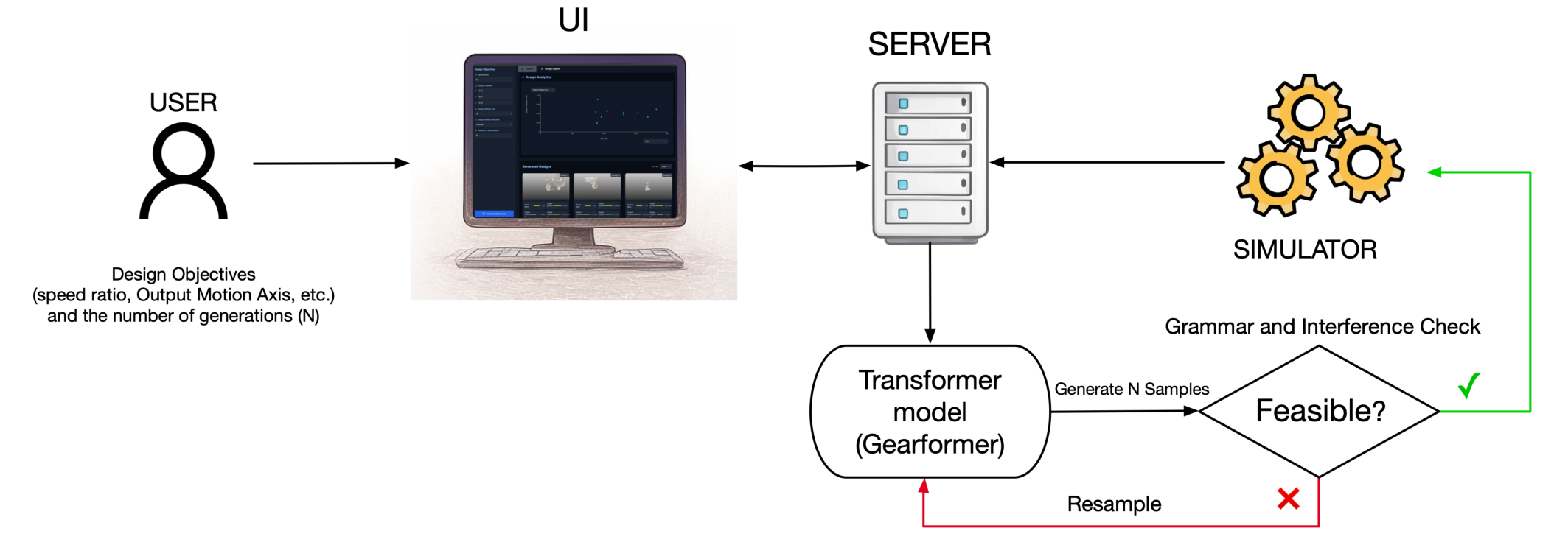
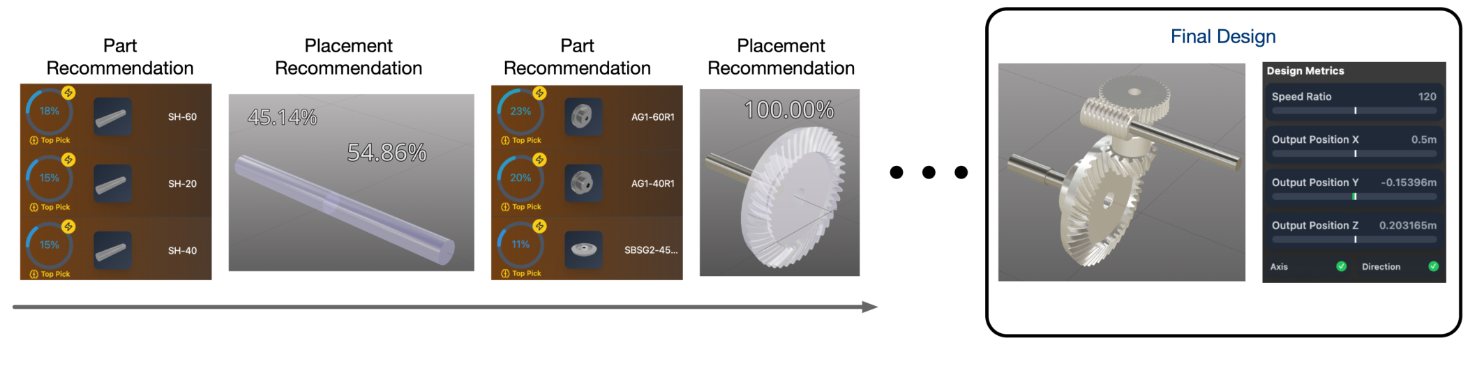
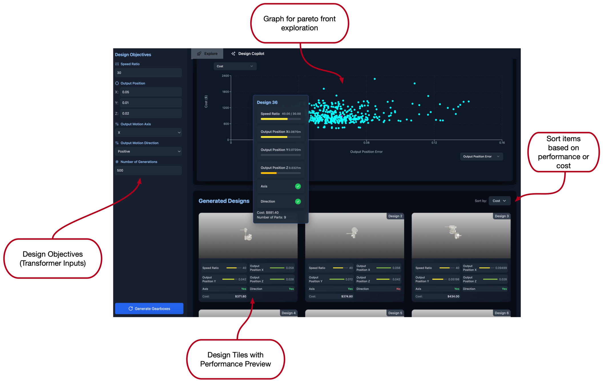
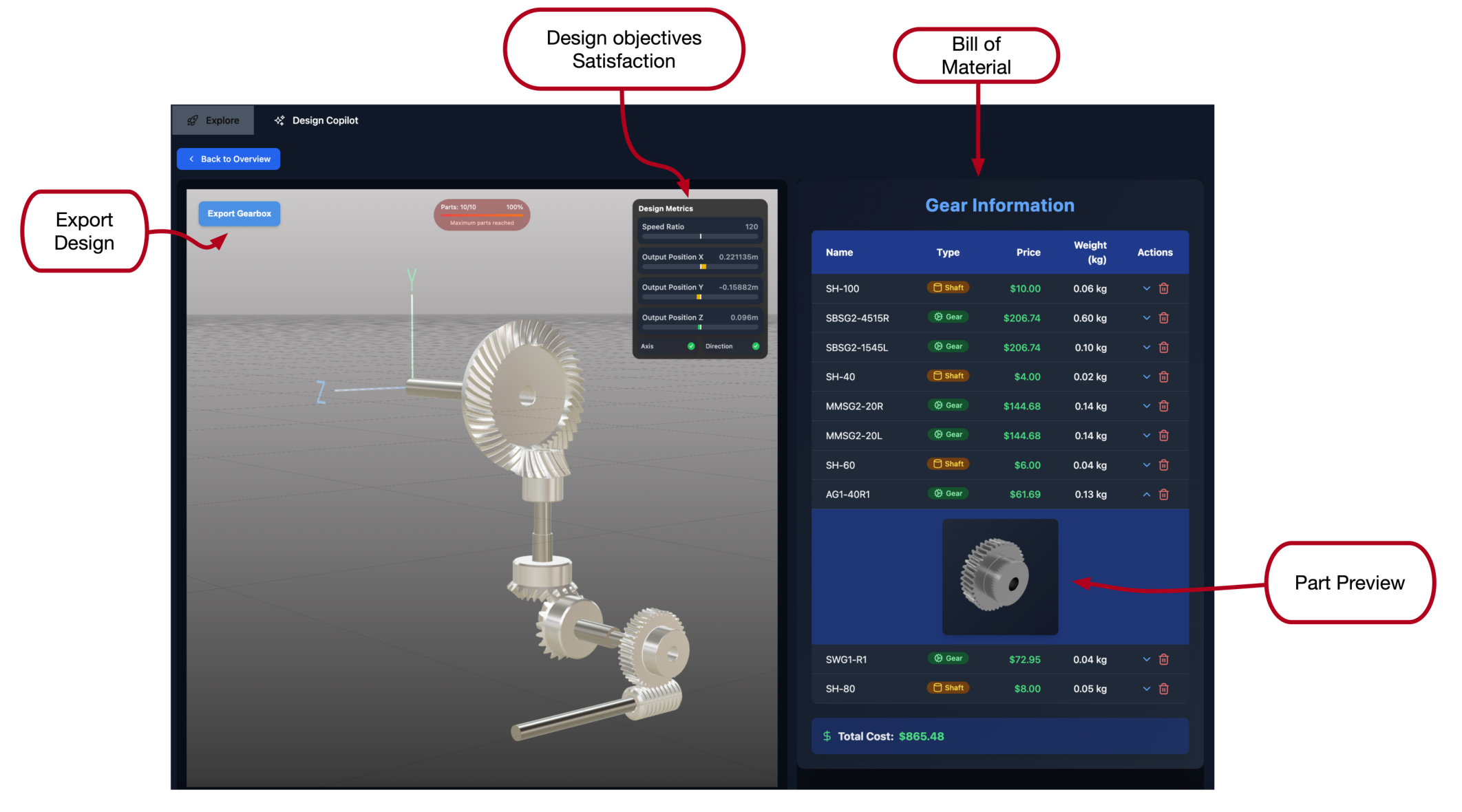
Generative artificial intelligence (AI), particularly transformer-based models, presents new opportunities for automating and augmenting engineering design workflows. However, effectively integrating these models into interactive tools requires careful interface design that leverages their unique capabilities. This paper introduces a transformer model tailored for gear train assembly design, paired with two novel interaction modes: Explore and Copilot. Explore Mode uses probabilistic sampling to generate and evaluate diverse design alternatives, while Copilot Mode utilizes autoregressive prediction to support iterative, context-aware refinement. These modes emphasize key transformer properties (sequence-based generation and probabilistic exploration) to facilitate intuitive and efficient human-AI collaboration. Through a case study, we demonstrate how well-designed interfaces can enhance engineers' ability to balance automation with domain expertise. A user study shows that Explore Mode supports rapid exploration and problem redefinition, while Copilot Mode provides greater control and fosters deeper engagement. Our results suggest that hybrid workflows combining both modes can effectively support complex, creative engineering design processes.

Figures

Figure 1: The Copilot Mode interface providing collaborative design refinement with GearFormer, featuring real-time 3D visualization (left), interactive design metrics panel (center top), and intelligent parts recommendation and selection interface (right).
Figure 2: An illustration of GearFormer’s inference process. A tokenized representation of the partially assembled gear mechanism is passed into a transformer model, which predicts the probability distribution over the next possible components. The next component is selected either as the most probable or by sampling from the distribution. The top predictions and their corresponding probabilities are shown on the right.
Figure 3: Schematic overview of Explore Mode’s sampling-based workflow. Users define design objectives and constraints,prompting GearFormer to generate multiple candidate assemblies, which are validat
Figure 4: Overview of Copilot Mode’s iterative design workflow. At each step, GearFormer provides ranked part and placement recommendations based on its autoregressive model. Designers select components and positions with confidence overlays, progressively building the assembly. Real-time feedback on feasibility and alignment with design objectives—such as speed ratio and output position—is shown alongside the evolving 3D model. The process continues until a complete, validated gear train is assembled.
Figure 5: Explore Mode interface, illustrating the Design Objectives panel for specifying transformer inputs (left), an interactivePareto front graph for visualizing trade-offs (top center), Generated
Figure 6: Detailed inspection interface for Explore Mode. A selected design is rendered in an interactive 3D view (left), displaying each gear and shaft. A Bill of Materials (right) lists individual components by name, cost, and weight, while a metrics panel (top center) reports how closely the design meets the user’s speed ratio and position targets.
Figure 7: Example of a gear placement with a confidence score overlay in Copilot Mode.
Figure 8: The yellow “Output” arrow visualizes the target position and orientation for the gear train output, serving as a spatial reference point for designers. This directional indicator helps users align their design with the required motion axis and position specified in the design objectives.
Figure 9: Example of a part usage indicator in the interface (here shown as 9 parts used out of a maximum 10). Exceed- ing the maximum limit can cause a transformer to produce inconsistent tokens due to context constraints.
Figure 10: Design task given to the participants.
Figure 11: For each respective mode, (a) average participant ratings [0-5] on their confidence in the designs generated and (b) number of participants who found a feasible solution that met all requirement metrics.
Figure 12: A feasible solution found by a participant (P6) with the Copilot Mode.
Figure 13: Participants’ preferences on the mode that 1) is easier to use, 2) helped gain more knowledge, and 3) they would use for everyday work.

BibTeX

@misc{ataei2025transformerbasedinterfacesmechanicalassembly,
      title={Transformer-Based Interfaces for Mechanical Assembly Design: A Gear Train Case Study}, 
      author={Mohammadmehdi Ataei and Hyunmin Cheong and Jiwon Jun and Justin Matejka and Alexander Tessier and George Fitzmaurice},
      year={2025},
      eprint={2504.08633},
      archivePrefix={arXiv},
      primaryClass={cs.HC},
      url={https://arxiv.org/abs/2504.08633}, 
}